
Introduction: Arduino: Filling Gaps for Project Based Learning and First Time Teachers


Objective:
This Instructable is aimed at first time Arduino technology teachers, students, and Makers, particularly for those involved in Project Based Learning. The objective is to fill in background on electric circuits and breadboards that typical Arduino tutorials assume is already known and overlook. While it will seem very basic to those with experience, it is unreasonable for teachers with no engineering background to have this knowledge. You may not realize the significance until buried in questions from students equally uninformed. It would seem that this background is essential for PBL students to be independent learners.
Background
I'm a retired technologist who has spent his career doing Project Based problem solving, and also a lifelong Maker/tinkerer with significant Arduino experience. Last school year ('03) I had the opportunity to substitute teach five high school level robotics classes for several months while the real teacher recovered from a serious operation. Even though I had no teaching experience, I was asked to fill in as traditional substitutes proved to be hopelessly clueless about everything Arduino.
This was an amazing experience! It provided me with the unique vantage point of a beginning Arduino-focused classroom, viewed from the perspective of my engineering design background. From the first day it became obvious that there were significant gaps between the assignments and the skills and knowledge of the students. Virtually every student could not build a working device after without asking for help, multiple times, even though it was not their first project. After giving some hints and answers the frequency of questions did not decrease, as you would expect. In fact their frustration and disinterest increased. This would seem to be a big negative factor in the ability of students to work independently on self-directed PBL projects. As a result, the objective of this instructable is to provide suggestions about how to fill the gaps to enable students to increase their independent success. The missing knowledge is not rocket science, it was just never provided.
Problem Assessment:
There seemed to be three fundamental problems. First, the students didn't really understand the most basic principles of electric circuit wiring. So they had no intuitive sense if what they were building made any sense. Second, they clearly didn't understand how their circuit breadboards, commonly used for wiring circuits, worked. So even copying a pre-drawn circuit always included a few mistakes because they were never taught the simple rules. While not really complicated, without sufficient explanation, their mistakes were unrecognizable, so they just kept repeating the same mistakes. Third, the situation could also be improved if the students were supplied with compatible materials that enhanced the convenience of building and changing their circuit wiring.
After reviewing a dozen online Arduino beginner tutorials, the source of the problem was obvious. The authors routinely took for granted an understanding of beginner circuit and breadboards knowledge. Almost all tutorials jump right into showing you finished code and pictures of circuits, assuming you don't need any preliminary explanation. The authors forgot how much they did not know them selves at the start. Since most K-12 teachers have little previous experience of circuits or breadboards, it is not surprising they did not identify these gaps, since they didn't know what they didn't know.
Supplies
- Arduino UNO Boards
- Small Breadboard (400 hole size)
Step 1: The Electric Circuit Power Sources

Electric circuits need a source of electric power. While most household appliances are powered by electricity from house plugs, the circuits you will be building will use much lower voltage. The circuits students will be building will typically use power supplied from the Arduino board.
The Arduino boards themselves are usually powered through the USB cable that connects to the laptop used for programming. They can also be powered by a 9 volt battery that plugs into the tubular socket. Less common, they can be connected to house plug power through a wall wart power reduction supply. These have a cord that plugs directly into the tubular socket on the Arduino. But be careful to use one that has voltage of 12 volts or less. Some computer wall warts are 18 volts and can be harmful.
The Arduino board has power reduction circuitry on it that further regulates the power and outputs it to terminals on the side of Arduino board that can be connected to circuit components. This will be explained in more detail later, but one terminal in the black pin strip is labeled 5v, which provides 5 volts positive (+) voltage. Right next to it is a terminal labeled GND. This is an abbreviation for "ground" which is called the negative (-) terminal. Ground is a term used by engineers to indicate a lower voltage terminal with 0 (zero) relative volts.
Step 2: Electricity Flows Through Closed Circuits


A fundamental concept students need to understand is that of a closed electric circuit. First, a common source of confusion about circuits needs to be cleared up. This is the notion of "plugging in" electric appliances. The usual experience is you just plug in ONE to energize a light bulb or motor. So it is easy to think only one wire is needed to turn on the light or any other thing electrical. Wrong!!
The cord connecting the appliance to the power source actually has two wires. When you plug it in, electrons flow in one wire, through the appliance or light, and return in a circular path to the source through the other wire. This circular path is called a closed electric circuit. So rather than just one wire to power something, it actually takes two wires.
While it is easy to get wound up in deep technical explanations about electrons, protons, charge, direction of flow, etc, these are unnecessary to be successful at wiring circuits and are going to bore art and English majors. As you can see the key concepts are very simple. There are great explanations in numerous elementary school-level YouTube videos and web sites. Reviewing one or more of these is a good place to start:
- https://www.youtube.com/watch?v=HOFp8bHTN30&authuser=0
- https://www.allaboutcircuits.com/textbook/direct-current/chpt-1/electric-circuits/
- https://www.windows2universe.org/spaceweather/how_circuit_works.html
An effective analogy frequently used is to relate the flow of electrons in electric current flowing through wires to water flowing through pipes. Much like water flows "through" pipes, electrons flow through wire in a closed circuit. One wire brings electric current from a source (e.g. battery, wall plug, or computer), it goes through a device, like a light bulb, motor, etc. and then a second wire completes the circular circuit by returning back to the source. The source in electric circuits can be a battery, think of it as like a pump in the water circuits that keeps the flow moving around again.
In the circuits students will be building, electricity flows from the + or positive side of the supply, through the circuit you will build, and back to the - or negative side. The important concept students often miss is that there must be an unbroken, circular, connection from from the + to - side to power the circuit. In my experience, this is an ah-ha moment and giant positive leap for beginners when they grasp the simple concept of needing to have a continuous, closed circuit!! This problem will be more clear when we talk about breadboards below.
An optional suggestion is to build this super simple circuit to get first hand experience. An example is shown here with a battery, knife switch, an small light bulb (not LED). The switch shown here is called a knife switch. While impractical for use in most projects, it has the advantage that the effect of opening and closing (or making and breaking) the circuit is completely visible with this type of switch. Even though these parts will not be used in Arduino constructions, because they are very inexpensive it is well worth having each student build their own copy. The "Oh, I get it now!" is worth it.
Summary:
- In your circuits you need two wires to make an LED light or other circuit work.
- The electricity goes along the wire in a circle through the LED, back into the battery and goes around again.
- The electrons are pushed by the electrons behind, making them all move at once
- There has to be a continuous path for the electricity to flow, like a continuous bicycle chain.
Step 3: Powering Circuits From Arduino's Power Supply

Most circuits students will build will be powered from 5 volts from an Arduino connected to an external power source, usually a laptop, 9 volt battery, or wall-wart. This is because most components used in basic projects only need 5 volts and Arduino's have a built in voltage regulator that reduces their external power to 5 volts. The role of the Arduino is usually to control when and for how long devices in circuits will receive power to turn on and off.
The first step is to connect a USB cable from a laptop to Arduino's silver jack. If correct, a small green LED should light up on the Arduino. This is a good sign, not a bad one.
Look at the labels on the pin connector on the left side of the Arduino board to locate the pin labeled 5v, this pin provides 5 volts from the internal power regulator on the Arduino board. Right below, locate the pin labeled GND. This is the Ground connection. To relate this to the explanation above, think of the 5v pin as like the positive side of a battery and the GND connection as the negative connection on a battery. Also, think of jumper wires as the same as the water pipes. As described above, the electric circuits you will be building will always form a loop from the 5v pin, through a connecting wire to the circuit on a breadboard, and then returning from the breadboard circuit through a wire to the GND pin on the Arduino.
A common convention is to use red wires to for positive connections and black wires for negative connections. This will help checking your wiring later. Connect a red jumper wire from the 5v pin on the Arduino to a hole in the red breadboard column on the right side. Next connect a black wire from the GND pin on the Arduino to a hole on the black breadboard column next to the red column. This will make the 5 volt power available on the breadboard. Just wire it exactly as described for now. The logic of the breadboard wiring will be explained below.
Step 4: Basic LED Circuit
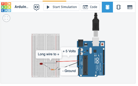
Next you will use the Arduino 5 volt supply to light an LED. While this will use a breadboard for making connections, the logic behind the breadboard connections will not be explained until the next step. So for now, just wire the breadboard exactly as shown in the diagram.
LEDs (light emitting diode) have a short wire and long wire. LED's are polarized, which means it makes a difference which way power flows through the LED. To connect them correctly, the long wire has to go to the + (positive) 5 v side of the power supply. The short wire has to go to the - (negative) side. If done incorrectly, the LED will not light. Getting these reversed is a very(!!) frequent problem for beginners and something to check first if one fails to light up.
For this construction, insert the LED wires into two holes in adjacent rows (as opposed to columns) on the breadboard, as shown in the diagram. Remember which has the long and short wires. Next, connect a black jumper wire from a hole in the same row with the short, black LED wire to a hole in the same column as the black (-) wire from the Arduino GND supply.
Finally, you need to include a resistor in the circuit. The details will be skipped until later, but LEDs will be burned out if the current through them is greater than 30 milliamps. In this case the current from the Arduino is to high and needs to be reduced FIRST by inserting a resistor in the circuit. To do this, insert one wire on a 220 ohm resistor (stripes red, red, brown) between a pin in the 5 v red column and the other end to a new row where the longer end wire of the LED is also inserted.
If done correctly, the LED should illuminate.
To clarify the concept of a closed electric circuit, use a finger to trace the current flow from the 5 v pin on Arduino board, through the red wire to a pin on the breadboard, then through the 220 ohm resistor to reduce the current, then into the LED, coming out through the other end of the LED, which is connected to the black wire that makes it way back to the GND pin on the Arduino. It should be a circular loop.
As a simple experiment, pull out the 5 volt, red. wire, that connects to the power supply on the Arduino. Notice that the LED goes out! That is because you have "broken" the connectivity of the circular circuit. Note that this is the same as what happens when you turn a light switch on and off. That also breaks the circuit. You will probably use a switch like that as a control in later construction projects.
Step 5: The Secret Side of Breadboards


Breadboards get their name because long ago engineers actually prototyped circuits by soldering wires and components between pins or nails pounded into real wooden breadboards. https://www.instructables.com/Use-a-real-Bread-Board-for-prototyping-your-circui/ Now that you have the experience of constructing a project on a breadboard, you probably also see how making correct connections on the breadboard can be confusing. Once you understand a few simple rules you will be able to easily make successful connections the first time. While most Arduino tutorials do not spend enough time explaining breadboards, there are many excellent video introductions. Three of those are listed here. By watching one or all of these you should get a good grasp of breadboard basics:
https://www.youtube.com/watch?v=W6mixXsn-Vc
https://www.youtube.com/watch?v=6WReFkfrUIk&authuser=0
https://www.youtube.com/watch?v=fq6U5Y14oM4
Look at the picture here of two breadboards where the cover has been removed from the back of one to expose the contacting metal strips described in the video. A useful classroom aid is to do this to a breadboard in your classroom and pass it around so the students can examine the back.
It is important to realize that the specific physical connections on your breadboard do not have to exactly match the wiring pictures. You can rearrange the components on the breadboard as long you follow the key rules in your adaptation the circuit is electrically equivalent and will still work:
- All the holes in the same column on the outside edges are connected
- All the holes in each row are connected
- But the holes in the rows do not connect to the holes in the column
- And the holes in rows next to each other do not connect
While these rules are very simple, it is easy to make mistakes. Here is a list of common errors:
- Not getting two connections in the same row, as they should be
- Getting the power (+) and ground (-) switched/mixed up
- Putting components in backwards/reversed
- Accidental short circuits by wrong connections
These three simple LED circuits built on breadboards have something wrong. Use your finger or a pencil to trace how the current would flow on each and see if you can figure out the problem.
Step 6: TinkerCAD Arduino Circuit Simulation


The first experience for most Arduino beginners is with an actual Arduino board connected to a laptop running the ArduinoIntegrated Development Environment (IDE). While that is how I learned myself, since then I've found that Autodesk's TinkerCAD is an excellent companion for both beginners and experts. For beginners it offers a way to easily build your Sketches by just dragging and dropping parts, simulating with the press of a button, and easily repair them with just a few mouse clicks, versus rewiring the physical board. Instead of getting power from the Arduino, the figure here show a 9 volt battery connected to an LED. The second figure show how a switch was easily added and can be simulated by pressing the button. As you get more experienced it is a very convenient way to quickly build, test, and modify prototypes as you progress through the implementation of a Project Based Learning experience.
Here are some great TinkerCAD tutorials:
Introduction to Tinkercad Circuits & Breadboarding
https://www.instructables.com/Basics-of-Arduino-TINKERCAD/
https://www.digikey.com/en/maker/blogs/2022/getting-started-with-tinkercad-circuits
Step 7: Ready, Set, Go!!!


Now that you have more background on electric circuits and breadboards you should be more prepared to inform students and handle their questions. Assuming this is your first experience with Arduino, here are a few suggestions for teachers to fill some gaps you may have about Arduino and classroom supplies.
- Arduino Boards
For beginner background, Arduino started in 2005 as a tool for students tool for students at the Interaction Design Institute Ivrea, Italy, to provide a low-cost and easy way to create devices that interact with their environment using sensors and actuators [1]. Since then, it has spawned an international do-it-yourself revolution in the open-source hardware and Maker movement, with about 30 million active students, hobbyists, designers and engineers across the world[2]. Because of its simplicity, accessibility, and affordability it is an excellent platform to use in STEM education.
- Get a Starter Kit for yourself
If this is your first time teaching an Arduino class, I highly suggest you invest in a personal Arduino Starter Kit because it is prepackaged with a complete set of compatible components. Think of buying this starter kit to educate yourself first, not to stock a classroom. If you are fortunate to take over a classroom fully stocked previously, you won't initially know what to pick and choose to get started. It is likely that it may be short from previous class use or have leftover options that don't match.
One of the best is the ELEGOO UNO Project Super Starter Kit:
It has a good set of components you need to get started for teaching a beginner class:
- UNO R3 Controller Board (see below), Breadboard, Power Supply Module, Servo Motor, Ultrasonic Sensor, 65 Jumper Wires, USB Cable; Buzzer, Button Switch, LEDs, and 220 ohm Resistors.
The ELEGOO kit has all these and more (relay, potentiometer, etc.), but you won't need these in an initial class. If you survey other kit options, some are cheaper and miss some key components, and some have many more components, but cost more. Don't be tempted to think more is better in this case.
- Classroom Arduino Board Options
The above startup kit comes with an Arduino UNO R3 microprocessor board. Since 2005, there are many different kinds of Arduino boards out there, but the UNO is the most commonly used in classes as it has greater online support than others. An Arduino Nano is a compatible option that is a smaller and cheaper than the UNO, but the small size is more difficult for beginners. Beyond your starter kit, you need to buy enough to have one Arduino dedicated to each student. You can get compatible clones for a fraction of the price of branded Arduino models from eBay, Amazon, Sparkfun,and AliExpress. It's important to understand that these aren't "cheap knock-offs", as they are made under an open source license. But if you are well funded and purchase an original, branded Arduino, a large portion of what you pay is donated by the Arduino foundation to fund educational outreach programs and further development.
- Breadboards
Breadboards are the second most important part of the Arduino constructions you will be building. You will be making devices that have electronic parts that have wire "leads" that are connected together to make electric circuits. You could build circuits without breadboard, but especially for beginners, they would work much slower. Breadboards are great for beginners and for prototyping new circuits since the connections are not permanent, so it is easy make changes or just start over and do a new project. They are simple devices designed to let you create circuits without soldering by pushing the leads into holes in the breadboard.
On the positive side, breadboards greatly speed up building and modifying student projects. But on the negative side, IMHO, they are explained too quickly at the very start, so most students just ask questions and never catch up. In my experience breadboard mistakes are the major source of project failures and student questions!!
Breadboards get their name because long ago engineers actually prototyped circuits by soldering wires and components between pings or nails pounded into real wooden breadboards. Modern breadboards are plastic with hundreds of holes with the same spacing (.1 inch) as the pins on integrated circuits. The holes have tiny metal strips underneath that grip wire when pushed into the holes. Some adjacent holes are connected underneath by the metal strips to connect wires electrically when pushed into neighbor holes. The most popular sizes are large 800 hole, and smaller 400 hole boards. The 400 hole size is more than adequate for starter class projects and less bulky. Each student will need one dedicated breadboard.
- Jumper Wires
Jumper wires are used for making circuit connections between components on your breadboard and your Arduino boards. Students will typically need about 6 or fewer wires, about 4-6 inches long, for most projects. The wires can be reused from project to project. While the color does not have any effect on the wire electrically, there are a couple of color coding conventions that are helpful to your constructions understandable. it is generally standard to use red wire for positive (+) connections and black wire for negative (-) power connections. Colors are not standard otherwise.
There are two popular options. One is to have students cut individual wires from long rolls of wire. The students will have to strip about 1/2 inch of the insulation off of each end so they can be inserted into the breadboard holes. The ideal wire is 22 gauge solid wire, as it fits best into the breadboards. The larger the gauge number, the smaller the wire. So be careful you do not get smaller wire (e.g.24 gauge) as it will slip out of the breadboard holes. Also get solid, not stranded wire. You can get this wire in long individual rolls or in boxes with 6 of different colors. Colors are helpful to differentiate between wire purposes. For example, red is typically for positive power and black is for negative. You can share 4 or 5 boxes in a class.
If you go this route you will also need wire strippers. Don't go with the most expensive. If you have about 5-6 strippers available, a typical classroom of students can get their wires cut and stripped in about 15 minutes.
- Jumper Wires with Pins
A second option, that I prefer, is to buy packages of premade jumper wires with metal pins attached to each end. This is what you will have in the suggested starter kit. While a little more expensive, this can save lot of class chaos by avoiding sharing cutting materials and the wires can be reused from project to project. They can be bought in assorted bunches of 100 for about $6 or less. Be sure you get a set with male-to-male connector pins. Don't scrimp when you are starting out, the worst thing is to run out of wires when students are building projects. So buy several bunches.
- USB to Arduino Cable
Many Arduino boards come packaged with one short cable to connect from the board to a computer USB port. These are usually about 12" long and colored blue. They will have a USB plug for a laptop connection and a special "barrel" jack for the Arduino board on the other end. But it is handy to have a few longer cables, usually 3 feet long, particularly for the teacher to set up demonstrations.
- Power Supplies
Your Arduino projects will need a source of power. Your starter kit will show you several options. The most convenient is to power the project through the same USB cable used to download software from the laptop. Just leave it connected after downloading and it will power the project. This is probably the easiest way for students to power their project builds. But the starter kit will show you two more options you may use sometime. One is a 9 volt battery connector that has a barrel-jack connector that can plug into the Arduino board after code has been downloaded. This can be convenient if a student wants to run a project without connection to a laptop. You should have one for each student.
A second is a 5 volt wall wort that plugs into wall plugs. You will probably seldom use this, but know it is available. But also be cautious if you use a different wall-wart that it is rated between 5 to 12 volts maximum. Some laptop wall-warts will have 18 or more volts. Be careful to keep those away as they can damage the Arduino.
- Project Platforms
A typical construction will consist of an Arduino board with wires connecting to a breadboard and sometimes to an additional component, like a servo motor or distance sensor. To avoid that becoming a cumbersome mess it is best to attach the Arduino and breadboard on a common platform. This can be any of several types of flat surface with a typical size of 5x7", but not much larger. There are many options, including pre-cut 3/16" sheets of Foam-core or thin 1/4" plywood sheets that may be available if a laser cutter is used nearby. These can be used over and over for each construction by just reconnecting the jumper wires between the Arduino and breadboard.
A first step in the class will be to mount an Arduino Uno board and a breadboard next to each other on the platform board. The Arduino board can be mounted with thick double stick tape. The breadboards come with an adhesive back side, so all you have to do is remove the cover plastic sheet and mount it on the board. For convenience in constructions it is best to mound the side of the Arduino with the longer black pin jack strip next to the breadboard. This will become obvious when you start connecting the two with jumper wired.
It can be convenient for the instructor to have at least one more durable platform for their own demonstrations, such as an RAB Baseplate. https://amzn.to/3su1BoD
- Project Boxes
It is convenient for the students to each have a dedicated project box to keep their project platform board and loose parts all in one container between classes. It is less of a hassle for the teacher if you provide each student with the same type of container to make storage and finding at the start of a class convenient. Plastic shoe box containers, or similar, are a convenient size and inexpensive. Each student can label the end of their box with their name on duct tape.
- Additional Parts
You will also at least one of each of these for each student:
- A 220 ohm Resistor
- An LED (any color)
- A 9 volt battery
- A battery connector
- A mini servo motor
- A Minimal Set of Tools
- Hot glue gun
- Wire strippers/cutters
- Screw Drivers
- Pliers
- What You Don't Need
Some articles and elaborate startup kits will recommend two things you definitely will not need. A soldering iron and multi-meter. Soldering irons are definitely needed to connect wires in more advanced circuit constructions, but in beginner classes you will be doing wiring on a solder-less breadboard. Multi-meters are often recommended by kit packagers, but it is an expensive gimmick to sell you something you will not use at this level. If you decide to get one later, Harbor Freight has one for $6
- Component Part Suppliers
For a tip on ordering stuff: Amazon is the usual go-to supplier for almost everything you will need for an Arduino class. Adafruit and Sparkfun are good sources for the most recent sensors and Arduino accessories and they usually have tutorials and sample code for their more complicated parts. More serious suppliers of electronic components are Digikey and Jameco. You can investigate cheaper alternatives from eBay, or aliexpress, a non-U.S. supplier with longer shipping times. Harbor Freight is a good source of low priced tools adequate for classroom use. Hobby stores that sell RC models are excellent sources of servo mounts, and connecting hardware. More advanced mechanical components can be found at servocity.com .
I hope this Instructable will be helpful for new teachers, but I also hope experienced teachers will write comments that I can use to correct or expand this information. Thanks and happy teaching!

This is an entry in the
Project-Based Learning Contest


Comments