Introduction: Plywood DML Speakers
Hello everyone
This is a little obsession of mine...
A few years ago I saw a video on Youtube about flat panel speakers and decided to have a go at making a pair.
After listening to my first very basic pair I was addicted to the sound, it's unlike anything I've ever experienced.
WHO KNEW VIBRATING A PIECE OF BOARD COULD SOUND SO GOOD!
Airy does not begin to describe DML's they are next level, I couldn't believe all the details in tracks that I've never heard before on conventional speakers.
And so my journey down the rabbit hole began, I now have a heap of panels that I've tested over the years... different materials, shapes, sizes, thicknesses, coatings... the list goes on and on, each small change makes a big impact on the sound.
When the time came to get some sound into my office I knew I had to have some kind of DML included in the system. My 4in bookshelf speakers was always a bit flat and lifeless so I decided to make some mid to high range DML panels to accompany them, although these panels can easily be used as full range drivers when accompanied by a small subwoofer as small flat panel speakers fall off below ~100Hz.
Join me on my journey of creating some small plywood DML panels...
Step 1: What's Needed:
Here's a list of everything needed with links:
- 2.5mm-3mm Plywood e.g. 3mm Plywood
- TEAX25C05-4/8 44mm Audio exciter
- Polyester resin + catalyst
- Access to a 3D printer
- ABS or PETG filament
- 2 Part CA glue
- 1mm Foam sheet
- 10mm aluminium pipe ( salvaged mine from an old antenna )
- At least 2M speaker cable
- Spray paint and filler primer
- Sanding paper
- *Access to a CNC router and laser engraver
*Optional
Step 2: What Is a DML Flat Panel Speaker:
"Distributed Mode Loudspeaker (DML) is a flat panel loudspeaker technology, developed by NXT, in which sound is produced by inducing uniformly distributed vibration modes in the panel through a special electro-acoustic exciter. Distributed mode loudspeakers function differently from most others, which typically produce sound by inducing pistonic motion in the diaphragm.
Exciters for distributed mode loudspeakers include, but are not limited to, moving coil and piezoelectric devices, and are placed to correspond to the natural resonant model of the panel.
Advantages:
-Broad frequency range (100 – 18000 Hz for 0.6m2 panel).
-The air radiation resistance is small and constant with frequency. This means that directivity is not affected by size of speaker.
-Bipolar (radiates sound in 2 directions), but may be made forward directed.
-Flat, don't require enclosing, may be produced in different shapes, may be decorated etc. Some DML units are designed to be plastered into walls and completely hidden.
-Low cost of materials relative to traditional loudspeaker designs."
Source - Wikipedia.org
Step 3: 3D Printed Parts:
We start by getting all the parts needed for the stand that will house the exciter and support the plywood panel printed.
All parts were made in Fusion 360, the design fits perfectly around a 44mm exciter if using any other model the file will need to be modified. When you want to increase the size of the panel you would have to increase the size of the base as well as changing the angle of the parts.
I've included the .stl and .f3d to make modifying the parts easy.
Because my speakers will be infront of a window that gets a lot of sun I decided to print the parts in ABS as PLA painted in a dark color would deform from the heat, they can also be printed in PETG or PLA in a light shade (I have no problems with white PLA prints in full sun).
My print:
0.6mm Nozzle
230 deg C nozzle 80 deg C bed for ABS+
.28 Layer height
Support only needed for the exciter housing, base prints without.
As with all my Instructables I've designed the parts to be as easy as possible to print on most household 3D printers with minimal material usage.
After my prints finished I gave all the parts a quick sand with 220 grit sanding paper to give the primer a better surface to grip onto.
Spray a few coats of filler primer onto the parts until the layer lines are covered.
Let the primer dry thoroughly and then start sanding the parts with 400 grit sanding paper and some soapy water.
Once you are happy with the finish on your sanded parts you can wipe them down with some alcohol and prepare them for a coat of paint.
I chose a classic piano black to fit with my bookshelf speakers, but remember if you printed in PLA to choose a light colour to reflect as much heat as possible.
When you are done with the printed parts we can start on the plywood panels and give the parts some time to dry properly.
Attachments
Step 4: The Whizzer Cone:
"A small supplementary cone attached to the voice coil of a speaker for the purpose of producing and radiating high frequency content more effectively than the larger speaker cone. A whizzer cone is attached to the voice coil in the same place as the speaker cone; however, where whizzer cones are used it is necessary for there to be some additional flexibility in the joint between the speaker cone in the voice coil. This allows the speaker cone to become somewhat decoupled from the higher frequency motion of the voice coil so it doesn’t dampen the voice coil from being able to move the whizzer cone at those higher rates."
Because I intended my DML panels to act as mid to high range drivers I decided to experiment with whizzer cones on the front of the panel, this gave quite a noticeable increase in spl in the upper range.
This took some trial and error as you have to resize the cones to the way you like the sound, at first I had them at 100mm outer diameter but this was way too big and gave a pretty tinny so I resized them to about 70mm outer diameter and 30mm high. This improved the sound quality heaps and it's how I kept it for a while and it's how it is in most of the pictures.
After listening for a while I noticed that with some songs at higher volumes the cones would start to resonate a bit. To print the whizzer cones I used PLA+ (PLA Pro/Premium) this fillament is a lot more flexible that normal PLA and the cone felt and sounded like a thin sheet of acetate, I immediately suspected this to be the culprit.
So I started with a new design and reduced the size again by 10% this time I decided to go with carbon fibre PLA, CF PLA is a lot stiffer with no flexibility and it has an almost cardboard like sound when knocking on it...PERFECT!
Now with the new whizzer cones i'm very happy with how they sound and I think they look a lot nicer with the carbon fibre.
Step 5: The Plywood Panel:
Attached is a SVG file of the cut for the panels.
The panels are:
250mm wide
290mm high
50mm fillet
I used a CNC with 1.5mm endmill to cut the panels but this can also be done with a laser or can just as easily be cut with a hobby knife if you don't have access to one of these machines.
After cutting I used some sanding paper to smooth out any rough edges left over.
Attachments
Step 6: LASERS!
This step is completely optional but to make it easier to align everything I decided to laser engrave a halftone dot pattern across the panel.
The pattern starts from the centre of the exciter also where you will attach the whizzer cone and go outwards, it will also help centre the panel later on.
Attached is the SVG files for both panels mirrored.
While I was busy engraving I decided to quickly cut out some 90mm circles from foam that I can stick on the bottom of the speakers to prevent rattling.
I used a cheap 500mw laser engraver on my CNC to do the engraving and cutting.
Step 7: Optional:
When I received my newest batch of exciters they had a round steel plate on the front of the voice coil for mounting. I thought this was quite neat as it made mounting a lot easier but after mounting them to a test panel I was very disappointed, the sound was muddy and had no output above 500Hz.
At first I thought it might be the panel material so I tried a few different panels, same result every time.
So it was time for a lil dissection...
Removing the plates turned out to be a lot more difficult than I anticipated, I started with a very thin blade and pried between the plate and the voice coil... be very careful!
When I had a small gap I dripped some isp alcohol on the joint to loosen the glue a bit, I was careful not to get alcohol on the rest of the exciter as I didn't want to risk dissolving any other glues.
Unfortunately on both of my exciters the plastic supporting ring below the plate also broke when I removed it so I decided to print a new ring that would then also be used to mount the exciter.
I used the same 2 part CA glue to stick the new ring onto the voice coil.
Placing the exciter with the new mounting ring onto the panel I was relieved that the sound I knew and loved was back.
Lesson learned metal mounting plates degrade the sound horribly.
Step 8: Stand Assembly:
We start with the 2 pieces of 10mm aluminium tube.
You want to drill a ~5mm hole just above where it will be exiting the base for the wiring to go through, I also made a notch at the top of the tube just so the wires go through easier behind the exciter.
After drilling the holes I put the tube into the chuck of the drill and let it slowly rotate whilst pressing some steel wool against it to give it a nice brushed aluminium look.
Next you can solder the wire onto your exciters making sure of the polarity on both drivers otherwise your speakers will be out of phase.
Now you can push the aluminium tube into the base and rotate it so that the hole you drilled is at the back, affix it using CA glue.
Do the same with the exciter housing, I used a piece of leftover plywood to align the housing with the base and glue into place.
Take your exciter and feed the wires through from the top and out of the drilled hole at the bottom.
Now add a generous amount of glue at the back of the exciter and push it into place.
Add a small piece of heat shrink around the wires exciting the tube and you're done with the stand.
Step 9: Plywood Treatment:
To protect the wood from moisture that will cause it to warp we need to seal it. A normal wood sealant or oil would dampen the wood panel and degrade the sound. So far the best solution I found was to coat the wood with a very thin hot coat of polyester resin.
First you want to sand the entire panel with 400 grit sandpaper, careful not to go too deep or you'll remove the laser pattern.
I used compressed air just to clean off all the dust from the panels after sanding.
Normally you would use a mix ratio of 2/100 with polyester but because this is such a thin layer I went with about a 5/100 ratio.
To coat both panels I used about 100ml of resin.
Mix your resin according to the manufacturers instructions (with additional catalyst if you prefer) and then wipe it onto the panels using a soft cloth like you would if oiling the wood.
Make sure the entire panel is covered because you only want to do one coat.
Set your panels aside and let them cure for at least a day.
Step 10: Panel Assembly:
Now the only step left is so assemble the plywood panel.
Because we want the panels to move as freely as possible I used a piece of leftover plywood as a spacer between the panel and the stand so that there's a 3mm gap for movement.
To attach the panel to the stand you will need to spread out a thin bead of silicone adhesive onto the base as pictured, to make this easier I squirt out a blob of adhesive on a piece of plastic and use a toothpick to apply it onto the base.
You will also need to apply a bead of CA glue around the mounting ring of the exciter, this is where it's important to use a 2 part CA glue as it gives you time to position your panel before drying.
Now with adhesive on both the exciter and the base you can position your panel in the centre of base and press it into place, don't push it completely flat against the base you'll want about a 1mm gap and remember the plywood spacer on the bottom.
Now make sure the exciter mounting ring is flush with the panel and then give it a spray with the activator to let it dry.
Next we want to attach the whizzer cone to the front of the panel.
Apply a very small bead of CA glue to the bottom (smaller ring) of the cone.
Now if you made it with the included circular design you can just line up the cone with the design otherwise you will want to make sure to place it over where the exciter is on the other side.
When its in place you can spray it with the CA activator.
And that's it, now leave the speakers to dry for a day and you'll be ready for your first listen.
Step 11: The Moment You've Been Waiting For!
And you're done!
Now it's time to hook these babies up and start cranking out the tunes.
They do take a while to run in fully and you will hear a change in the sound as the resin on the panels continue to cure over the next few days.
Please share your creations with me and happy making!
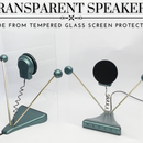
Step 12: Updated With New Whizzer Cones:
Here are the DML panels with the updated carbon fibre PLA whizzer cones, I think they look pretty swanky.

Runner Up in the
Plywood Challenge









22 Comments
Question 2 years ago on Step 11
Has anyone tried using acoustical ceiling tiles?
2 years ago
These are awesome. I am currently building a house and would like to create a larger pair of these for the space. I was just curious if you had explored any sort of wall mounting configuration for these?
2 years ago
Lovely! I want to make these :)
Reply 2 years ago
Thank you, you definately should!
2 years ago
Very impressive design!!! I loved it!
Reply 2 years ago
Thank you very much.
2 years ago
“WHO KNEW VIBRATING A PIECE OF BOARD COULD SOUND SO GOOD!”
Pretty much everyone who has ever played, listened to, or made a piano, violin, guitar, oud, etc.
Reply 2 years ago
The difference between the instruments you have listed, and the instructable you just read is that those instruments are not vibrating wood. Those instruments rely on the vibrations of strings. The wood that the instruments are made of help to resonate and amplify the sound, but the wood is not creating the sound. In this tutorial, the wood is vibrating to make the sound, instead of a wire. Please do not criticise someone else's hard work unless you actually know what you are talking about.
Reply 2 years ago
Touché...I should have been more clear, rather who thought craft store ply or cardboard could sound so good.
2 years ago
For sealing the panels, have you considered or tested shellac?
Polyester resin seems like overkill to me but then I do not have your experience with this.
I'm very seriously considering this on my project pile for my now permanent work at home office!
Reply 2 years ago
I definitely want to try shellac, unfortunately I'm struggling to find any locally. Also if you are able to find some tone woods give that a try too.
Reply 2 years ago
Shellac is not that hard to find here in Australia and I know of many places you can buy it in the USA. That said, I do not know where you are located so a little hard to offer more specific advice.
I do know you can buy it through Amazon.com.au. I imagine their other local stores probably also have it.
Depending on what look you are going for, I would start with dewaxed super blonde. It's almost water clear when applied.
Tone woods as an option is an interesting idea. I will give that some thought.
2 years ago
Very impressive! I think I saw the same Tech Ingredients YT videos you used as inspiration -- one of my favorite sites for sure. Two questions, if I may: The curved cutout on the bottom of your plywood sheets - is that to help the panels "move" while the silicone adhesive keeps them fixed to the stand or is it just a design element? Could a screw or two surrounded by soft rubber grommets replace the silicone? That would allow disassembly without having to cut through a line of silicone each time.
Reply 2 years ago
Also if you are starting out with DML panels before cutting your plywood, start by placing the exciters on the larger sheets. This will give you an idea of how they sound. If space isn't an issue large DML panels sound AMAZING!
Reply 2 years ago
Thank you, yes my thoughts behind the cutout was to increase the flexibility above the joint. I think a screw would work with some thread lock added as these panels vibrate quite aggressively. Another option is to use some double sided tape, it's easier to remove and still allows movement.
Reply 2 years ago
I have the same question about the intent of the curved slot... functional or design element?
But I can't imagine needing to disassemble speakers very often, if ever. Once you got them sounding good... do not disturb the assembly...
2 years ago
I rarely post comments on instructables but this one is quite compelling and inspiring! Thank you for sharing!
Reply 2 years ago
Thank you.
2 years ago on Step 12
VERY Nice! Thanks for sharing...
Reply 2 years ago
Thank you very much.