
Introduction: Mr.Engraver : the Desktop Laser Engraving Machine


Meet "Mr.Engraver" ! The DIY portable desktop laser engraving machine. The Engraver can engrave on wood and plastic, Cut through foam sheets and paper. The machine can be used to do tons of creative work, the only limit is Imagination (besides the work area).
The work area of Mr-Engraver is 38mm x 38mm. The whole machine was built , while keeping Laser safety in mind. I have built a cabinet for the machine. This protects the user from direct viewing. And know what ... its equipped with the "Automatic laser shutdown"
What is Automatic shutdown?
Class 3B and higher power lasers can be harmful when viewed with naked eyes. So I thought to block the rays by building a cabinet. But what if someone accidentally opens the door while the system in working? Here's where the Auto Shutdown plays its role. When the door is opened, the limit switch cuts off the power of the laser immediately shutting off the laser.
For this instructable we will be building our own Laser Focusing Module from scratch... You may ask "Why not simply buy the already made module? One could buy an Aixiz housing off eBay.. But what challenge is that? Also Building is fun, you can learn a lot while making... and proudly say that you have made it!
The crystal clear prints of the laser have impressed me. I am still engraving a lot and will share the results with you when I get a masterpiece!
~
Snapchat and Instagram: @chitlangesahas
I'd love to connect with you guys on Snapchat and Instagram, I document the experience, learning lessons and also answer questions on those platforms. Looking forward to connect! Here is my username for both: @chitlangesahas

-----------------------------------------------------------------------------------------
While making the Engraver machine, I had a lots of failures, earlier with the axes movement and later with the Laser extraction and focusing. Read the whole story in last step.... Innovation is messy...!
"I have not failed ... I've just discovered 1000 new ways that wont work " --- Thomas Edison
Quick Review:
1) 250mW Red Laser Diode
2) Ventilation fan to drive out smoke
3) Laser Safe design
4) Laser Auto shutdown
Ready to get your hands dirty? Lets begin!
------------------------------------------------------------------------------------------
If you like this project you can reward me by using your shutter clicking skills by sharing my work to all your friends. In return, I'll cook up more Instructables to share with you. Any suggestions or queries are welcome in the comments. Thanks for your support!
Step 1: Watch the Video :
Here is the HD video of "Mr-Engraver"
Step 2: Bill of Materials


The materials you will need to build this CNC are :
1) L - Braces --- x 2
2) CD or DVD RW --- x3
3) EasyDriver Modules --- x3
4) Arduino Uno (any flavour works) --- x1
5) Plywood
6) Leather roll
7) 12V 3A SMPS power supply --- x1
8) Basic Building stuff (Screws, Nuts, soldering Iron ,and a Creative Mind )
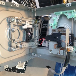
Step 3: Take Apart the ROM's


The first step is pretty easy. Rip apart the ROM's to salvage the rails. We need the 3 rails to drive the three axis.
Also remember to save the metal casing as we are going to deal with it shortly.
There are many other useful parts to get from the ROM's like
1) Laser Diode on the sled
2) DC motors
3) Interesting Optical materials -- The lens, etc - can be used to take really interesting macro shots-- worth a try!
4) Strong Neodymium Magnets -- Found near the laser focusing unit on the sled
Step 4: Build the Y Axis


Once we have extracted the rails and the casing lets get to work! First step is to build the Y axis...
1)Mark the holes on one of the metal Casing Box (got it why i wanted you to save those?)
2)Drill the holes with a 5mm metal drill bit and sand the "Burrs"
3) Also Drill the two holes for the "L Braces" on the opposite edge of the metal casing. (Refer the photos)
We will add the Platform later...
NOTERemember to position the Y axis as straight and close to the edge as possible. Any large deviations in the placement will lead to weird images in the final results.
Step 5: Build the Z Axis


Time to build the Z axis of the CNC.
1) Cut a piece of Poly carbonate Sheet of a appropriate size. The piece should be just enough for the Z axis to accommodate.
2) Drill the 4 holes on the vertices and one on the center of the sheet exactly
3) With help of some screws nuts and washers secure the Z axis on the poly-carbonate Sheet.
Again! Be careful with the alignment of the Z axis, It should be straight as possible.
Tip : I chose Poly-carbonate because it has low density so will be light in weight. This is important as the Stepper motors of the ROM's cant lift weights.
Step 6: Combine the Z Axis and X Axis and Mount Them


Once we have built the Y axis and the Z axis, Now take the Z axis and mount it on the X axis.
1) Slowly make a hole on the X axis's Sled *
2) Now slowly drive a Screw into the Sled so that the screw thread "bite" into the plastic.
3) Remove the screw we drove in (2) and mount the Z axis onto the X axis.
4) Add a generous amount of hot glue on to the joint of X and Z axis this will protect them from turning.
5) For accuracy I hot-glued two washers on the sled ,before mounting the Z and X axis , to keep it aligned. The washers keep the screws and ultimately the whole axis from distorting. I recommend this step.
6) Take both the axes (X and Z) and mount it on another metal casing Box, as straight and close to edge as possible.
## BE EXTREMELY GENTLE on the Sled while tightening the screws. My sled had split into two parts due to overturning. Later I had to glue them with lots of hot glue.
Step 7: Y Axis Bed


The Bed in terms of CNC is defined as the platform where the Object to be worked on, is kept. I chose Poly carbonate sheet to make the Bed.
1) Cut a small yet appropriate size of poly carbonate sheet.
2) Sand of the burrs on the piece.
3) Drill a 5mm hole exactly in the Middle of the sheet.
4) Fix the screw into the bed with washers and nuts.
5) Now, Drive a spare screw into the Y axis Sled, again Be Gentle, The threads on the screw will bite into the plastic sled.
6) Mount the bed on to the sled.
## Make sure the BED is mounted with enough gaps between the Stepper and the poly. sheet so that they don't jam.
** Remember to mount the Y axis bed exactly parallel to the Y axis SLED. Deviations will end up in unwanted results.
" Do not Over tighten the screws"
Step 8: Combining All Three Axes...


Once we are ready with all the axes, mount them at 90 degrees with help of "L-Braces".
1) Adjust the axes perpendicular to each other.
Make sure the Y axis doesn't crash into the Z axis.
2) Drill the holes into the metal case of the ROM..
3) With nuts and bolts secure the axes with L-Braces.
Note: Make sure the axes are perpendicular, I am repeating this because I mean it, you wont get the desirable results until the alignment is perfect.
Step 9: Make the Control Circuit


We have built the "Hands and Feet" of the CNC. But we need a brain to control the Hands and the feet.
We are using Arduino Uno , (any flavor works.) as the brain of the CNC,
1) Build the circuit as described in the Picture 1.
2) Connect the respective axes steppers motors to their drivers. Here is a quick table:
Axis X Y Z
E.D pins ------------ (GND) (STEP) (DIR)------------
ARDUINO (GND, 2,5) (GND, 3,6) (GND 4,7)
(digital pins)
3) Connect the Power Pins
4) Recheck the Connections
5) We are placing the circuit at the back of the X and Z Axis Case. This will make it portable.
6) Wire a relay driver circuit to the arduino pin 12 to control the laser.
Step 10: Ventillation Fan for the Stepper Drivers


The EasyDrivers go Crazy Hot while in operation. We need a way to cool them down.
1) Take the back-plate cover of the CD ROM casing and Mark a 6X6 holes equidistant according to the size of fan.
2) Drill out the holes
3) Sand off any metal burrs.
4) Attach the fan to the metal case.
This attachment will act as a back plate for our CNC Body.
5) Wire the fan to appropriate 12V connections and then install the back-plate to the CNC Body.
Step 11: Install the GRBL Library
Okay ... so we got the hands, feet and the brain, Here's the Soul! The step is to flash the arduino with GRBL library.
1) Download the GRBL library provided below.
2) Extract and Copy the whole folder to the arduino main folder ex : C:\Program Files (x86)\Arduino\libraries
3) Open the Arduino IDE and navigate to File>>Examples>>GRBL and click GRBL.
4) Click the Upload button to flash the library to arduino... of course connect your arduino board to the computer...

Step 12: Build the Laser Module


To make a laser module assembly, we are going to build it from scratch. One could buy a axiz Laser Housing off eBay which comes with everything. But... what challenge is that.?
Sorry, I don't have enough photos during the making of the laser module. although I have included a 3D Cad design so that everything is clear to you.
There are two major steps 1) Extracting the laser diode from the DVD Writer.
2) Building a focus-able housing and a Laser Driver
1) EXTRACT THE DIODE :
You will need a DVD Writer for the extraction of the diode, CD ROM's wont work ,.
1) Carefully extract the laser diode from the sled of the DVD Rom.
2) You can also salvage many useful stuff from the track like lens, we will need one for the housing we are building next
If you are lucky and skillful enough, you should get the diode out safely. I had to scavenge FIVE DVD writers before I could get it to work. ! Remember :
Only those who dare to fail greatly can ever achieve greatly....
## Don't apply unnecessary pressure on the diode, this may damage it. Also see Laser Safety instructions before doing any thing with the laser(in next few steps).
2) BUILD The housing and Driver:
1) Take a small 6V Dc motor, you will find inside the ROM's
2) Dig in and extract everything to Salvage the outer case of the Motor.
3) With some thermal paste, secure the Laser diode. The Motor case acts as a heat-sink.
4) On a washer, glue a lens from the sled to the washer Hole.
5) Using small screws and springs from a ball point pen attach the washer (with lens) to the motor casing and........
VOILA ! we got a makeshift laser housing for cheap... This Idea was inspired by the instructable :
https://www.instructables.com/id/Homemade-laser-mod... by pinomelean
I made a laser driver using LM317. Constant current was ranged up-to 350mA.
## Don't Exceed the current supply above 400mA, The diode doesn't have a good heat-sink and will eventually burn out if current exceeds.
Step 13: Laser Mounting


I mounted the laser on the z axis following the steps below:
1) Using my old toy "Mechanics", I made a attachment to the z axis sled.
2) I used hot glue to mount the fixture.
3) Next, I soldered a small hose clamp, to the fixture and this is it!
Step 14: Laser Controll


The laser control circuit is as above:
First picture is of the relay control through arduino.
Second picture is the Laser Driver. Wire the driver to the relay and power pins to controll the laser.
Step 15: Laser Safety

The laser we are using in the project is a Class 3B laser. This laser can cause serious damages is misused or handled carelessly.
I must say " Don't underestimate the power of a LASER!" The power rating of the lasers seems like " Only 300mW? What can a 300mW cause to me?" Yes ! the laser can burn your eyes if you are not careful....
Understand the risks:
Class 3B
A Class 3B laser is hazardous if the eye is exposed directly, but diffuse reflections such as those from paper or other matte surfaces are not harmful. Protective eye-wear is typically required where direct viewing of a class 3B laser beam may occur. Class-3B lasers must be equipped with a key switch and a safety interlock. Class 3B lasers are used inside CD and DVD writers, although the writer unit itself is class 1 because the laser light cannot leave the unit.
Use safety goggles to protect yourself from the laser radiation.
"Accidents hurt - safety doesn't"
Step 16: Build the Cabinet :


For a professional look and added protection from the laser beams we are opting for a Wooden cabinet,
I measured the CNC dimensions and built a wooden box. I chose a cute curved design to maintain the aesthetics of the Machine.
The 3D design of the cabinet
Again guys, I couldn't take many pics while building, but i am sure the 3D design helps you get the point....
1) Cut the plywood according to design..
2) Nail them together ..
3) Sand off any nail heads and rough wood edges
4) Form the front door with a flexible plywood and hinges .
5) Add door magnets to hold the door in place.
6) Attach a small drawer handle to the door.
Remember to drill a hole in the cabinet for power wires to pass through.
Step 17: Ventillation Fan...

To keep things inside the cabinet cool, we will add a fan to it..
1) Mark a few holes on the cabinet.
2) Drill them with 6mm bit
3) Attach a 230V mini exhaust Fan.
Step 18: Some Leatherwork..


To add a bit of elegance to the Cabinet, lets add a touch of leather to it.
1) Cut leather of appropriate dimensions (sizes may vary for you)..
2) Using Synthetic Rubber (SR) adhesive, apply all leather pieces to the body.
3) Once dried, poke the holes in the leather, for the vent. fan
Tip: Form clean cuts so that final looks are appealing. Use all your creativity, patience and take your time. Things go messy but the final look is worth it.
** Use the Glue in a well ventilated area, the smell from the drying SR glue causes nausea and headache.
Step 19: Laser Safety : Automatic Shutdown

So ... Got the risks involved in the project? What about safety? Yes... We care about safety and are going to design a automatic shutdown system for the laser.
How it works?
We are going to add a limit switch to the door of the laser CNC. Once the door is opened the Limit switch is deactivated and the laser shuts off. This system can be very useful as accidental opening of the door (by the kids) will shut off the laser.
1) Take a limit switch and position it on on of the walls such that when the door is closed, the switch is turned on.
2) Using hot glue secure the switch.
3) Wire the Switch in series between the Driver and power supply (Not driver and laser diode).
This step seems optional but will prove to be very useful in case of an accidental opening of the door.
"Prevention better than cure,"
Step 20: Power Supply:


Wheres the juice? here it is...
1) Pass a power cable through the hole.
2) Screw on the terminals of power cable to the power supply.
3) Power the 230V fan from the same line.
NOTE: Be careful to wire the polarity of the drivers, the easy driver doesn't have any reverse protection.
Step 21: The Early Failures


I started the project, hoping to build a PEN plotter, a "draw-bot" which could actually draw with a pen. I got my model ready. The first few trials were weird Images. Circle looked like stairs.!
I did much of troubleshooting and found that updating the GRBL Library solved the problem.
Later, I caught interest in attaching a laser to make a engraver. I googled and found that a burning laser could be made out of old DVD writer. But I had to literally open up FIVE DVD Writers before I could a working diode.
Further, the challenge was to focus the Laser. I hardly had any knowledge of focusing by then. And also the laser heat could melt any normal adhesive which I would use to hold the lens in place. So I extracted the lens from DVD Sled, got a Heat prof Adhesive and got the focusing to work.
More to add, Due to overturning , the sled had split into two. I had to pour lots of glue to restore it.. Amazing experiences ...
While building this project I failed a lot of times, but definitely I learnt a good lesson:
"Failures are a part of life, If you don't fail , you wont learn and if you don't learn you will never change."
Step 22: Final Results..
Here are the masterpieces from the laser engraver. The machine we just built has endless possibilities. The only limitation is the work area 38mm x 38mm. But at an entry level, a person who wants to take a gist of world of CNC's , this project is fun to build.
Time to say good bye... :)
Hey friends, time to say goodbye to all of you. We had a great time. If you love this project perhaps you like some of my others. Do check them out. Also tell me what do you think of this project, Any suggestions or questions ? Post them in the comments, I will be glad to answer them. Good Bye !

Participated in the
Robotics Contest

Participated in the
Homemade Gifts Contest 2015

Participated in the
Tech Contest


42 Comments
6 years ago
awesome!! i want to build one right now.
6 years ago
nice engraver...check mine also..
7 years ago
Great Project ! how can i contact you . i wanted to do Make in India project with you.
You may contact nkm160164@yahoo.com
Do you live in India , which location.
Thanks
Naresh
Reply 7 years ago
Wow! Good to know!
Well check your mail , I have sent my location.
Thanks for your comment.!
7 years ago
Awesome! Looks like a lot of work was put into this project!
I have to try using "Sketchfab"... :)
7 years ago
Great Project!!
7 years ago
Hey!! Bro I really love picture quality of ur instrucatbles!! Which camera/lightening u use??
7 years ago
from where you found the easy stepper motor drivers ?
as I saw on explorelabs.com and they are for rs. 1000 each and I saw one of your comment as total build cost was around 2500rs.. so can you provide the link to order . pls dont give me ebay.com as I have already wasted 2000rs for 5stepper drivers and I have not got the delivery.
7 years ago
Would this work on glass or would I need to find a different kind of laser engraver?
Amazing work by the way :)
Reply 7 years ago
Thanks
Reply 7 years ago
To my knowledge, you dont need a "different kind" of laser engraver. The axis setup remains same what changes is the laser power. I think a higher power laser will be required.
7 years ago
Great Work !
Reply 7 years ago
thanks:)
7 years ago
what is tentative cost in INR
Reply 7 years ago
Around 2500 rs
7 years ago
Step 14: Laser Control?
I am not sure how the driver and the control circuits are connected? - could you provide some more details? Perhabs a full schematic from arduino to laser head.
What is the big blue box? - a relay?
Thanks - very interesting and good intructable.
Reply 7 years ago
Let me explain you in brief :
First of all the pin 12 on the arduino is the spindle control. This pin outputs +5 V when the spindle (in our case, laser) is to be turned on. The pin outputs 0 v when turned off.
The outputs are controlled by the grbl code. If you see an example, you will find some text like : M03 and M05 03 is turn on and 05 is off.
What we are doing is connecting a transistor to pin #12 so that we are able to drive a relay circuit. the relay then turns on and off, the laser.
To sum up :
Arduino #12 => Transistor =>Relay => Laser driver=> laser.
Thanks for your interest.
Sahas.
7 years ago
Hello,
Is it possible to use UNL2003 motor drive board instead of EasyDriver?
7 years ago
Hello. great project. I tray made it for my self. X, Y axis work fine but i have problem with laser. Can you give me more detail how you wired the laser, lm317 and arduino. How you know which laser is the right one in dvd, usually is 2 laser in dvd burner. thank
Reply 7 years ago
See the steps for laser control. I have added the instructions in the instructables:)